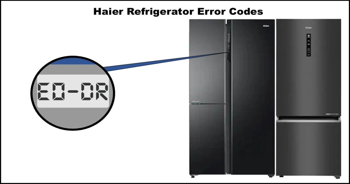
Seeing an error code flashing on your Haier refrigerator display can be concerning. Don’t panic! Many common issues can be diagnosed and sometimes resolved with a few troubleshooting steps. This guide will walk you through the common Haier refrigerator error codes, their potential causes, and steps you can take to identify the problem.
⚠️ IMPORTANT SAFETY WARNING ⚠️
Before attempting ANY troubleshooting steps that involve accessing wiring or components, you MUST unplug your refrigerator from the power outlet. Working on an appliance connected to power can lead to serious electric shock. If you are uncomfortable performing any of these checks, or if the problem persists, always call a qualified appliance repair technician. This guide is for informational purposes only.
Common Haier Refrigerator Error Codes
Initial Step: Power Cycle
Sometimes, a simple reset can clear temporary glitches. Try unplugging your refrigerator, waiting for 5 minutes, and plugging it back in. If the error code reappears, proceed with the specific troubleshooting steps below.
Sensor-Related Errors (F1, F2, F3, F4, F5, F6, Fr, EH)
These codes indicate a problem with one of the temperature sensors within the refrigerator system. The system detects that the sensor circuit is either open (broken connection) or shorted (incorrect connection).
Common Causes:
- Faulty sensor itself
- Loose or damaged wiring/harness connector
- Faulty Main Control Board (PCB)
Troubleshooting Steps:
- Inspect the Wiring: Locate the relevant sensor (see list below) and check its wiring harness connector. Ensure it’s securely plugged in and look for any visible damage or corrosion.
- Check Sensor Resistance: Using a multimeter set to Ohms (Ω), measure the resistance across the sensor’s terminals. Compare the reading to the expected value for its approximate current temperature. A reading that is infinite (OL – Open Loop) or very close to zero usually indicates a faulty sensor that needs replacement.
- Note: Sensor resistance changes with temperature. The values below are reference points.
- Check Main PCB: If the sensor and wiring seem okay, the issue might lie with the Main Control Board (PCB). This usually requires professional diagnosis and replacement.
Specific Sensor Codes & Resistance Values:
- F1: Refrigerator Defrost Sensor
- Expected Resistance: ~1.960 KΩ at 25°C (77°F)
- F2: Ambient Temperature Sensor (Measures room temperature)
- Expected Resistance: ~6.350 KΩ at 0°C (32°F)
- F3: Refrigerator Sensor (Measures fridge compartment temperature)
- Expected Resistance: ~6.350 KΩ at 0°C (32°F)
- F4: Freezer Sensor (Measures freezer compartment temperature)
- Expected Resistance: ~6.48 KΩ at 0°C (32°F)
- F5: Variable Temperature Zone Sensor (If applicable)
- Expected Resistance: ~6.48 KΩ at 0°C (32°F)
- F6: Freezer Defrost Sensor
- Expected Resistance: ~6.48 KΩ at 0°C (32°F)
- Fr: Main Sensor (Specific function may vary by model)
- Expected Resistance: ~6.48 KΩ at 0°C (32°F)
- EH: Temperature Sensor Error (Often relates to a specific zone or function, check model specifics)
- Troubleshooting Note: For EH, also check the voltage at the hinge connector (if applicable). It should be between 0.9v and 4.5v. If outside this range, suspect the Main PCB.
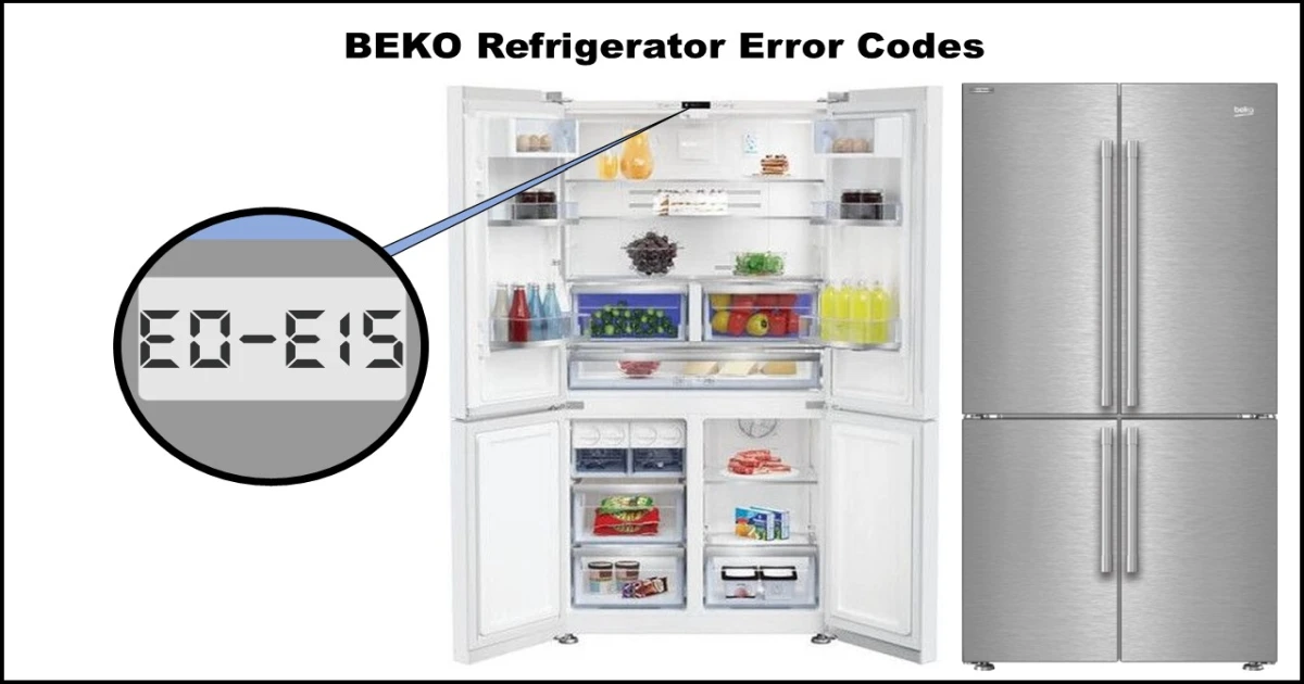
Communication Error (E0)
This code signifies a communication failure between the main control board (PCB) and the display board.
Common Causes:
- Damaged wire harness connecting the boards
- Faulty display board
- Faulty Main PCB
Troubleshooting Steps:
- Check Wiring: Inspect the harness connector between the main PCB and the display board for damage or loose connections.
- Inspect Boards: Visually check both the display board and the main PCB for any signs of damage (burn marks, corrosion).
- Professional Diagnosis: Diagnosing whether the display or main PCB (or both) is faulty often requires specialized testing. Sometimes, replacing both boards simultaneously is recommended if the specific faulty board cannot be isolated.
Fan Motor Errors (E1, E2, E6, E9)
These errors point to a problem with one of the fans responsible for circulating cold air.
Common Causes:
- Fan blade obstruction (usually ice buildup)
- Faulty fan motor
- Faulty Main PCB not supplying power to the fan
Troubleshooting Steps:
- Check for Obstructions: Access the fan (see list below) and check if its blades are blocked by ice or debris. Carefully defrost any ice buildup if found.
- Check Voltage Supply (Requires Caution – Professional Recommended): At the Main PCB connector for the specific fan motor, check the DC voltage supply. It should typically be between 7V and 12V DC. If the voltage reads 0V DC, the Main PCB is likely faulty.
- Check Fan Feedback Voltage (Requires Caution – Professional Recommended): Check the fan’s feedback voltage signal back to the PCB. This confirms if the fan is running and reporting its speed correctly. Expected values are around 2.4 Vdc when the main voltage is ~11.3 Vdc (values may vary slightly).
- Replace Components: Based on the checks, replace the faulty fan motor or the Main PCB.
Specific Fan Codes:
- E1: Freezer Fan Motor
- E2: Condenser Fan Motor (Located near the compressor at the back/bottom)
- E6: Refrigerator Fan Motor
- E9: Variable Temperature Zone Fan Motor (If applicable)
Defrost System Errors (FD, RD, HD)
These codes indicate a failure in the defrost system for a specific compartment, preventing the removal of frost buildup from the evaporator coils.
Common Causes:
- Damaged wiring harness
- Faulty thermo-fuse (safety device that cuts power if the heater gets too hot)
- Faulty defrost heater (Open circuit or shorted)
- Faulty Main PCB
Troubleshooting Steps:
- Check Defrost Circuit Components: Access the evaporator coils for the affected compartment (this usually involves removing panels inside the freezer or fridge).
- Thermo-Fuse: Check for continuity using a multimeter. It should read near 0 Ω (closed circuit). If it reads infinite/OL (Open Loop), it’s blown and needs replacement.
- Defrost Heater: Check its resistance. Compare it to the expected value (see below). An infinite/OL reading means the heater is faulty.
- Check Voltage Supply (Requires Caution – Professional Recommended): During a defrost cycle (which may need to be manually initiated – “forced defrost mode”), check for AC voltage (e.g., 220 VAC or 120 VAC depending on your region/model) at the defrost heater connector on the Main PCB. No voltage suggests a Main PCB issue or wiring problem. Voltage present but heater/fuse check failed points to those components.
- Forced Defrost Test: If components seem okay, initiate a forced defrost cycle (consult your model’s service manual for instructions). If the defrost heater activates, the repair might be complete (perhaps an intermittent connection). If it doesn’t activate despite components testing okay, suspect the Main PCB.
Specific Defrost Codes & Heater Values:
- FD: Freezer Defrosting Error
- Heater Resistance: ~270 Ω (Side-by-Side) or ~403 Ω (Multi-Door) – Values are approximate.
- Thermo-fuse Resistance: ~0.1 – 1 Ω (Good), ∞ Ω / OL (Faulty)
- RD: Refrigerator Defrosting Error
- Heater Resistance: ~403 Ω – Approximate value.
- Thermo-fuse Resistance: ~0.1 – 1 Ω (Good), ∞ Ω / OL (Faulty)
- HD: Variable Temperature Zone Defrosting Error (If applicable)
- Heater Resistance: ~403 Ω – Approximate value.
- Thermo-fuse Resistance: ~0.1 – 1 Ω (Good), ∞ Ω / OL (Faulty)
Door Switch Errors (DF, DR, DH)
These errors suggest the refrigerator isn’t correctly detecting whether a specific door is open or closed.
Common Causes:
- Door switch physically stuck, loose, or damaged
- Damaged wiring harness
- Faulty door switch
Troubleshooting Steps:
- Inspect Switch: Locate the door switch for the relevant door. Check if it’s loose, physically damaged, or stuck. Press it manually to see if it moves freely.
- Check Switch Resistance: Use a multimeter to check the switch’s continuity.
- When Door is Open: The switch contacts should typically be closed (reading near 0 Ω).
- When Door is Closed: The switch contacts should typically be open (reading infinite/OL Ω).
- If the switch doesn’t behave as expected, it needs replacement.
- Check Voltage (DH Code Specific): For the Variable Temperature door (DH), you can also check the DC voltage at the Main PCB connector for the switch:
- Door Open: Should read 0 Vdc.
- Door Closed: Should read 5 Vdc.
- Incorrect readings point towards a faulty switch or wiring issue.
Specific Door Codes:
- DF: Freezer Door Error
- DR: Refrigerator Door Error
- DH: Variable Temperature Zone Door Error (If applicable)
When to Call a Professional
While this guide covers common issues, refrigerator repair can be complex and involve potentially hazardous voltages. You should contact Haier customer support or a qualified appliance repair technician if:
- You are uncomfortable performing any of these checks.
- The error code persists after troubleshooting.
- You suspect a faulty Main Control Board (PCB).
- Multiple error codes are present.
- The issue requires handling refrigerant (this legally requires certified technicians).
Remember, safety first! Don’t attempt repairs beyond your comfort level or expertise.
