Troubleshoot Your Whirlpool Refrigerator’s Issues: A Comprehensive Guide to Service Diagnostic Mode
One of the challenges in diagnosing Whirlpool refrigerator’s issues is the absence of visible error codes during normal operation. Fortunately, many Whirlpool models feature a hidden service diagnostic mode that provides valuable insights into the refrigerator’s health and helps pinpoint the source of a malfunction.
This Whirlpool refrigerator service diagnostic mode guide will walk you through accessing and utilizing this powerful diagnostic tool, empowering you to understand what might be wrong with your refrigerator and potentially facilitate a quicker and more efficient repair process.
What is Service Diagnostic Mode?
Service diagnostic mode is a special operational state designed for troubleshooting electronic appliances. When activated, it allows the refrigerator’s control system to perform self-tests on various components and functions. The results of these tests are typically displayed on the user interface, providing technicians (or a determined DIYer) with specific information that can help diagnose problems that aren’t immediately obvious.
Important Safety Precautions:
Before entering the service diagnostic mode or attempting any troubleshooting or repair, ALWAYS unplug your refrigerator or disconnect power at the breaker. There are live electrical components within the appliance, and failing to disconnect power can result in serious injury or electrical shock.
Voltage measurements should only be performed by authorized technicians using appropriate safety equipment.
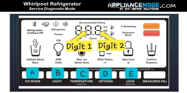
How to Access the Whirlpool Refrigerator Service Diagnostic Mode
The exact buttons used to enter diagnostic mode can vary slightly depending on your specific Whirlpool model. It is highly recommended to consult your refrigerator’s technical sheet if you have it. This document, often found behind the kick plate or inside the control panel, will provide the precise instructions for your model.
However, a common method for many models involves simultaneously pressing and holding two specific buttons on the control panel for a few seconds. Let’s refer to these as Button A and Button B for this guide.
- Ensure the refrigerator is not in “Control Lock” mode.
- Press and hold Button A and Button B simultaneously for approximately 3 seconds.
- Release both buttons when you hear a chime or see a change on the display, often a 3-2-1 countdown.
- The display should show “01”, indicating you have successfully entered the first step of the diagnostic process.
Exiting Service Diagnostic Mode:
You can exit the service diagnostic mode at any time using one of the following methods:
- Press and hold Button A and Button B simultaneously for 3 seconds.
- Unplug the appliance from the power outlet or turn off the circuit breaker.
- In some models, the mode will automatically time out after a period of inactivity (e.g., 20 minutes).
Navigating the Diagnostic Steps:
Once in service diagnostic mode, you will typically use other buttons to navigate through the various test steps and control component activation. Let’s refer to these as Button C, Button D, and Button E. Again, consult your tech sheet for the exact button functions on your model.
- Button E: Use this button to move to the next test step or skip the current step.
- Button D: Use this button to return to the previous test step.
- Button C: Use this button to activate or cycle through the functions of the component being tested in the current step (e.g., turn a fan on or off, cycle a damper).
The display will usually show a two-digit number indicating the current step number. An orange light may illuminate during the step number display, and a red light might indicate the test result.
Understanding the Test Cycle Steps:
The service diagnostic mode runs through a series of tests to check different components. The specific steps and their order can vary by model. Below is a general overview of common test steps you might encounter:
Cooling System Diagnostics (Typically Steps 01-07, 32-39):
These steps focus on the components responsible for cooling your refrigerator and freezer.
- Step 01: Freezer Compartment Sensor Test.
- Checks the freezer thermistor (temperature sensor).
- Step Result: Displays a code indicating the sensor’s condition (e.g., 01 for good, 02 for open circuit, 03 for closed circuit).
- Troubleshooting: If an error code appears, check the sensor’s wiring harness for damage or loose connections. Measure the thermistor’s resistance with a multimeter and compare it to the temperature-resistance chart provided in your tech sheet. Replace the sensor if the resistance is out of range.
- Step 02: Refrigerator Compartment Sensor Test.
- Checks the refrigerator thermistor.
- Step Result: Similar to Step 01, indicates sensor condition.
- Troubleshooting: Follow the same steps as for the freezer sensor, checking the wiring and measuring resistance.
- Step 03: Evaporator Fan Motor and Air Baffle Motor Test.
- Activates the freezer and refrigerator evaporator fans and the pantry air baffle.
- Function Behavior: Use Button C to cycle through different fan and damper states (e.g., both off, freezer fan on, refrigerator fan on, damper open/closed, both fans on). The display will show corresponding codes (e.g., 01, 02, 03, 04 for fan states; 13 for damper open, 23 for damper closed).
- Troubleshooting: Verify airflow from the fans and check if the damper opens and closes. If a fan or damper isn’t working, check its wire harness, inspect for physical obstructions (like ice buildup on fan blades or a stuck damper), and test for proper voltage at the motor or damper assembly (perform voltage tests with caution and only if qualified).
- Step 04: Compressor, Condenser, and Evaporator Fan Test.
- This is a longer test that cycles the compressor, condenser fan (usually runs when the compressor is on), and evaporator fans to check the sealed system’s operation. There might be a delay before this test begins.
- Function Behavior: The test progresses through different stages (e.g., initializing valves, starting compressor, cycling refrigerant flow to freezer and refrigerator evaporators). The display will show progression codes (e.g., 01, 02, 03, 04, 05). Note: This test may not be interruptible once started and can take several minutes.
- Troubleshooting: Listen for the compressor running and feel for vibrations. Check that the condenser fan is operating. Verify refrigerant flow by feeling the evaporator coils (with caution and only if qualified) as the test cycles between compartments. If there are issues, it could indicate problems with the compressor, fans, a faulty valve, a refrigerant leak, or a restriction in the sealed system. These often require a qualified technician.
- Step 05: Compressor Speed Test.
- Tests the compressor’s ability to run at different speeds (if applicable).
- Step Result: Codes may indicate the current speed (e.g., 02 for medium, 01 for full). Use Button C to cycle through speeds.
- Troubleshooting: If the compressor doesn’t change speeds as expected, it could indicate an issue with the inverter board or the compressor itself.
- Step 06: Defrost Heater, Bimetal, and Sensor Test.
- Checks the defrost system components.
- Step Result: Codes indicate the status of the bimetal thermostat (e.g., 01 for closed, 02 for open). You may be able to activate the defrost heater using Button C.
- Troubleshooting: An open bimetal when cold indicates a potential issue. Check the wiring harnesses for the defrost heater, bimetal, and defrost thermistor. Measure the resistance of these components and compare to the chart in your tech sheet. A faulty bimetal, heater, or thermistor can prevent the refrigerator from defrosting properly, leading to ice buildup.
- Step 07: Defrost Mode Setting.
- Allows you to view or change the defrost mode setting (e.g., Adaptive Defrost Control (ADC) or timed defrost).
- Step Result: Codes indicate the current setting (e.g., 01 for ADC, 02 for basic timed defrost). Use Button C to toggle the setting.
- Troubleshooting: This step is typically for configuration rather than diagnosing a specific fault, though ensuring the correct defrost mode is selected can be part of resolving icing issues.
- Steps 32-39: These steps may include tests for additional sensors like the ambient sensor, humidity sensor, ice box sensor, and refrigerator evaporator sensor, following similar diagnostic procedures as Steps 01 and 02.
Dispensing and Ice Making Diagnostics (Typically Steps 08-31, 45-60):
These steps verify the operation of the ice maker and water dispenser systems.
- Step 08: Display Test.
- Turns on all LED indicators and display digits to check their functionality.
- Step 11: Dispenser LED Setting.
- Allows adjustment of the dispenser light brightness using Button C.
- Step 15: Ice Level Sensor Test.
- Checks the ice level sensor in the ice bin.
- Step Result: Codes indicate whether the bin is detected as full or not full (e.g., 01 for full, 02 for not full).
- Step 16: Freezer Compartment Door Switch Test.
- Checks the freezer door switch.
- Step Result: Codes change based on whether the door is open or closed (e.g., 02 for closed, 01 for open).
- Step 17: Refrigerator Compartment Door Switch Test.
- Checks the refrigerator door switch.
- Step Result: Similar to Step 16 for the refrigerator door.
- Step 18: Ice Door Motor Test.
- Tests the motor that opens and closes the ice dispenser door.
- Step Result: Codes indicate the door’s position (e.g., 01 for closed, 02 for opening, 03 for open, 04 for closing).
- Step 19: Ice Maker Fill Tube Heater Status.
- Checks or allows activation of the heater that prevents the ice maker fill tube from freezing.
- Step Result: Codes indicate if the heater is on or off. Use Button C to toggle.
- Troubleshooting: If the fill tube is freezing, check the heater’s wiring and measure its resistance.
- Step 36: Ice Box Fan Test.
- Tests the fan located in the ice box (if applicable).
- Step Result: Codes indicate if the fan is on or off. Use Button C to toggle.
- Troubleshooting: Check wiring and fan blade if the fan isn’t running.
- Step 37: Ice Box Sensor Test.
- Checks the temperature sensor in the ice box.
- Step Result: Similar to other thermistor tests (Step 01, 02).
- Troubleshooting: Check wiring and measure resistance if an error code appears.
- Step 38: Forced Defrost Mode.
- Manually initiates a defrost cycle.
- Step Result: Options for short or long defrost may be available (e.g., SH, LO).
- Troubleshooting: Useful for melting ice buildup on the evaporator coils to see if normal operation resumes afterward.
- Step 39: Refrigerator Evaporator Sensor Test.
- Checks the temperature sensor on the refrigerator evaporator coil.
- Step Result: Similar to other thermistor tests.
- Troubleshooting: Check wiring and measure resistance.
- Step 45: Ice Maker Water Fill Test.
- Tests the water fill valve for the ice maker. It’s often recommended to perform an ice maker harvest cycle (Step 57) before this test.
- Function Behavior: Use Button C to cycle through states like off, filling, and pause.
- Troubleshooting: If the ice maker doesn’t fill, check the water valve’s wiring harness, water filter, water line (for freezing or clogs), and the valve’s resistance. If water runs continuously when it shouldn’t, the valve might be faulty or the main control board’s relay for the valve could be stuck.
- Step 46: Water Dispensing Test.
- Tests the water fill valve for the dispenser.
- Function Behavior: Use Button C to cycle through off and fill states.
- Troubleshooting: Similar checks as Step 45, also including the dispenser switch and water reservoir.
- Step 56: Ice Maker Error Codes.
- Displays stored error codes related to the ice maker.
- Possible Outcomes: The display will show specific error codes (e.g., E0-E5) with meanings related to cooling issues, home position loss, heater timeouts, dry cycles, or thermistor faults.
- Troubleshooting: The guide provides specific actions to take for each error code, often directing you to other diagnostic steps to test relevant components.
- Step 57: Ice Maker Harvest.
- Initiates an ice maker harvest cycle.
- Function Behavior: Use Button C to cycle through heater activation and motor rotation to eject ice.
- Step Result: Codes indicate the sequence and completion status.
- Step 58: Ice Maker Heater and Thermistor Test.
- Tests the ice maker mold heater and thermistor.
- Function Behavior: Use Button C to toggle the heater.
- Step Result: Codes indicate heater status and thermistor temperature or fault.
- Troubleshooting: Check wiring and component resistance if issues are found.
- Step 59: Ice Maker Motor Test.
- Tests the ice maker’s motor for rotation in both clockwise (CW) and counter-clockwise (CCW) directions.
- Function Behavior: Use Button C to cycle through motor states and directions.
- Step Result: Codes indicate motor status and completion.
- Troubleshooting: If the motor doesn’t rotate, check wiring or consider replacing the ice maker assembly.
Other Potential Diagnostic Steps (Step numbers may vary):
- Step 65: Pantry Thermistor Test.
- Checks the temperature sensor in the pantry or deli drawer. Similar troubleshooting to other thermistor tests.
- Step 73: Pantry Heater Status.
- Checks or allows activation of a heater in the pantry (if applicable).
- Step 77: Defrost Thermistor Test.
- Checks the thermistor specifically used for monitoring the defrost cycle temperature. Similar troubleshooting to other thermistor tests.
General Troubleshooting Tips After Running Diagnostics:
- Note Down Results: Carefully record the step numbers and the results displayed for any tests that indicate a fault (codes other than “01” for sensors, or unexpected behavior during component activation).
- Consult Your Tech Sheet: Your refrigerator’s technical sheet is the most accurate resource for interpreting diagnostic codes and troubleshooting steps for your specific model. It often includes wiring diagrams and component specifications (like resistance values).
- Inspect Suspect Components: If a diagnostic test points to a specific component (e.g., a fan, sensor, or valve), visually inspect it and its wiring harness for any obvious damage, disconnections, or obstructions.
- Perform Resistance Checks: If you are comfortable and have the necessary tools, use a multimeter (with the power UNPLUGGED) to measure the resistance of thermistors, heaters, and motor windings and compare the readings to the specifications in your tech sheet.
- Consider Professional Help: If you are not comfortable performing electrical tests, cannot identify the issue, or the repair requires accessing sealed system components (which contain refrigerant and require specialized tools and knowledge), it is best to contact a qualified appliance technician.
Conclusion:
While Whirlpool refrigerators may not display user-friendly error codes during normal operation, the service diagnostic mode is a valuable tool for uncovering the root cause of many malfunctions. By understanding how to access and navigate this mode, and by carefully interpreting the test results in conjunction with your appliance’s technical sheet, you can gain significant insight into the problem. Remember to prioritize safety by always disconnecting power before inspecting or servicing components. With this knowledge, you’ll be better equipped to address issues with your Whirlpool refrigerator, whether you choose to perform the repair yourself or call in a professional